Charger - BMS wire harness instalation SX-02240
1. Remove NiMH charger data harness VEC5000 - refer to SX-000209
2. Push harness S02240 (1) between frame and glove box and further through frame hole as shown in the picture below
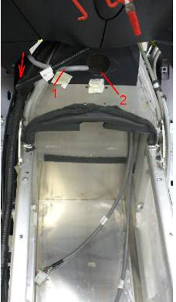
3. Connect harness 2240 connector to main wire harness ( P2 J3) and fasten it into front subframe (1) with zip-ties.
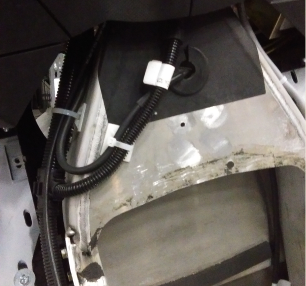
4. Install frame hole gasket (1) and zip-tie new harness
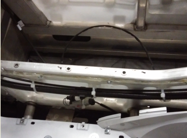
5. Attach main harness and seat cable to the frame with new zip-ties.
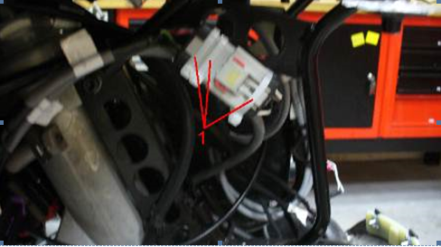
6. Disconnect main wire harness from Motorcontroller (plug J22)
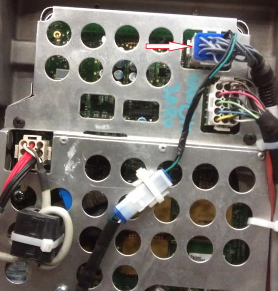
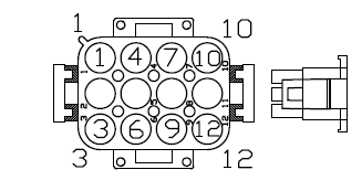
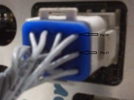
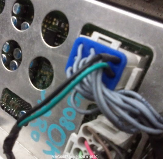
7. Using AMP pin extraction tool ST1200 - remove pin 10 and 11 from connector J22. Mark wires 10 and 11 for resembling.
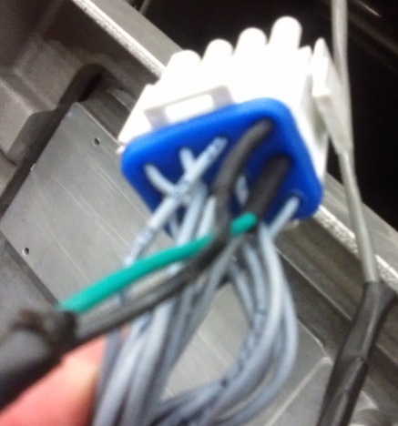
8. Attach supplied CAN-MC patch to wires (by soldering or re-crimping with new supplied pins). Black wire from patch to wire in pin 10, green wire from patch to wire in pin 11. Both new and existing wires connected to one pin pass trough blue gasket and install in the connector.
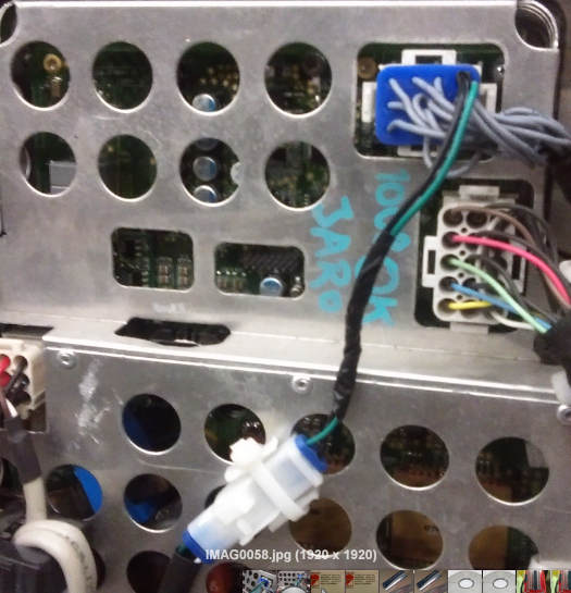
9. Connect the main harness (with the patch) to the motocontroller
10. Connect installed patch with corresponding terminal on new harness 02240 and zip-tie to MC cover.
Customer support service by UserEcho
On the CAN-MC patch to wires cable I have the wires are black and red. Can I assume black goes to black and red goes to green?
Yes