Charger Types - compatibility with Lithium Batteries SX-BC-CONV
Vectrix VX-1 is equipped with 1.5kW onboard charger.
Since 2007 there were 3 types of chargers in use:
1. ESD (silver) charger with round connectors
2. ESD (silver) charger with square connectors
3. EVPS (Runke, gold) charger in various revisions (from 1.0 to 4.0)
EVPS (Runke) charger revision 1.9 or higher (2.0, 2.1, 2.1N, 3.0, 4.0) is fully compatible with BMS used in Lithium batteries. We recommend revision 3.0 or 4.0 as most reliable.
ESD chargers requaires bord modification - refer to ESD Charger Upgrade to Li
EVPS chargers earlier then 1.9 - for example 1.7 requaire controll board replacement - refer to EVPS Board 1.9
Chargers identification.
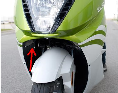
First step identyfication (ESD vs EVPS) can be performed without disassembling scooter:
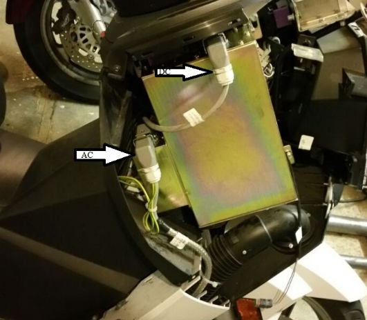
ESD charger has aluminium housing in silver / gray color, double cooling fan and both connectors (AC and DC) on the bottom.
EVPS (Runke) Chargers have metal housing in gold color, single cooling fan and connectors on top:
ESD Charger revision is coded in the serial number of charger.
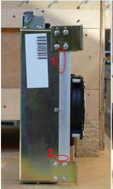
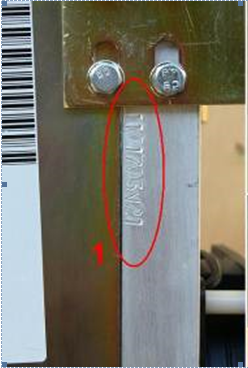
If serial number includes V20, V21 or V30 - this is the revision (2.0, 2.1, 3.0)
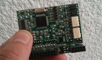
If serial number does not include letter V - it is requaired to open the charger housing and inspect controll board. Board compatible with Li software - 1.9 looks like this:
Customer support service by UserEcho
hello piotr
I have a vectrix vx1 li+ but my battery are died.
So I would like to transform my lifepo4 by cells panasonic NCR18650B.
My charger is a gold with serial V21, I have 4 BMS board with 10 connections Each for 10 cells.
Can I reused these BMS board with only 8 cells (36s and not 40s before with the lifepo4) and use your box adaptator following http://shop.vectrixparts.com/vx1-bms-adaptor-pcb-case.html
Thanks a lot for your help
Clement
yes you can just cell 9 or 10 need to be shorted with the upper cell of the module.
Hello Mateo
Thanks for your feedback, In attachment, I have drown a battery modification, you are ok with this schematic ? Thanks clement
If you will use it with the adaptor board bought from us we can prepare the adaptor to suit you.
Generally - V10 and V9 has to connected to V8 (positive)
Regards
Hi Piotr,
I am trying to determine the compatibility of my charger and even though your tekst has already been very helpfull, it did leave me with a few questions.
You explicitly mention revisions and their different compatibilities for Runke chargers.
You also mention that there are two different ESD chargers and that ESD chargers require board modifications.
Then however you demonstrate how to identify the revision of ESD chargers and what boards are compatible with Li software - 1.9,
and in your webshop you sell ESD Silver Charger v2.0 for Ni and Li weighting 10KG as well as offer a service to upgrade the ESD charger to Li weighting 12KG.
--
- Are there stock ESD chargers that are compatible with both Ni and Li, or do only modded ESD chargers support both? (What ESD chargers are compatible with both NI and Li?)
- Is the 10 KG li + Ni capable ESD charger from your webshop a modded charger, and why is it 2 KG lighter then the original ESD charger that could be send to you for modding?
Regards
Berend
ESD chargers (silver with aluminium casting and double fan) - there are two types - round connectors and square connectors. There is no other difference between them. Both need a controll board upgrade to use with Li batteries. To be frank though, we don't reccomend them at all for Li batteries - at the last stage of charging, when cell balancing is done at the very low current (0.3A) ESD chargers sometimes freeze, sometimes fail completly.For NiMH batteries it is a great charger though - if housing is sealed with silicon it can last forever.
EVPS (Runke) chargers are in gold square box, with single fan - they were manufactured between 2009 and 2013 in vew revisions 1.5, 1.9, 2.0, 2.0N, 3.0, and there was a revision 3.0NFD sold by us only. In general it is not a good quality charger, some power diodes on main board fail quite often, sometimes another few components around resulting with NO Ouput failure. We were selling these chargers afer reworking / upgrading them (added fuese on AC side, better diode, changed some resistor etc). We still have some stock of them - used mostly for older bikes / warranty purpose.Look for S00540 in our online shop (www.shop.vectrixparts.com) - it comes with warranty and is upgraded to the best we coudl do with this hardware.
If you have Li scooter or planning conversion - we strongly reccomend new type of charger 3.3.kW TC charger - available in our shop online (S00541). It is not cheap but realy worth its price - fully enclosed IP67, manufactured in thousands for an electric cars, zero failure rate after selling over 200 of them, completly quite and double power (half time to charge) comparing to ESD/EVPS.
Is the picture above for using original bms-boards in 36s setup instead of 40s setup right?
I'm doing a similar conversion with samsung INR18650-25R cells.
Great resource this forum ;o)
Hi Gunther,
Yes, you can use original BMS boards in both configuration(36s and 40s). Differences are in connection and software configuration.
hello piotr or Mateo
I have 2 questions :
- I cannot communicated with the ICM board (red in the diagnostic soft), it’s possible to send you the ICM board and reprogramming the PIC ?
- I want convert the vx1 with 52Ah, but it’s possible to configure the charger with this power ? How I can configure the soft?
Thanks for your feedback
Clément
Clement
Yes you can send us the ICM board - we will try to repair it.
What charger do you have?
Hello Piotr
Thanks for your feedback, but I have bought a pic debugger and I succeed to debug the ICM board.
Thanks
Clement
Hi Peter, I'm currently running 19 Leaf modules with latest Dugas firmware. It's 2007 VX1 with ESD charger. No other mods on a bike. Would you please suggest what options I have for the BMS from you?
Andrei.
Sorry, spell checker, Piotr...
Hello Piotr,
I'm new here though it's my second WX 1. never modified exept by a reseller during warranty time ( fast charger now)
in about 6 years and 2 VX: 1rst problem....:)
No more charging. Stops after few seconds and displaying : high 430 low 292.
after several tries, charging came back for 1 time only.
a former owner of VX 1 helped me.
result is on photo.
I guess I shoul change 1 cell, maybe two. or is it a BMS mistake? and can I easily slow down the charging current to make batteries last longer?
Thank you.
P.S. VX is given for 180km and Itried successfully 140 when I bought it (used, 1000 KM)
After trying contacting Vecrix team over email, posting here, opening a private ticket, nobody came back to me. So, don't spend your time waiting for the reply here.
Hi,
The charger firmware aborts the charging process if any of the measured cell values - in fact any of the four High Cell values - are above 4.2 V. This is for safety reasons.
Your problem in the 4.209 V on that block, that needs to be fixed. Since the block under it shows as 3.941 V it is quite possible the small wires that are used for the measurement have a minor contact problem distorting the values measured by the BMS.
The BMS is simply a 4x9 channel multimeter (ADC) in its default state when the balancing is inactive.
/ Azzuro
Thank you very much Azzuro.
the next question is:
Fisrt step: opening VX to check cables
2) recheck cells with canbus
3) check the cell with a multimeter
4) if really above 4.2, slightly and slowly dichage the cell with the right resistance value (U=R*I) let's say 100mA R= 4/0.1=40 ohms 0.5 watts.
5) restart charger when cell is around 4.08
Am I right?
If it restarts, I'll try if a cell goes down again under 2.92 riding. As it did as first symptom. Before charging worked 1 time only after several tries .
Thank you.
Almost :) You can skip the step 2 - the values you see in the Diag are based on CAN bus.
3) Check all suspected cells with a multimeter when the Vectrix is off and while it is on
4) Check the respective cell measuring points on the BMS card
The next step can be decided based on the results.
Hello Azzuro,
Back with my problem. I checked all I could (even inside theBMS wich had a internal plug slightly moving). swapped the two DB25 plugs. The problem swapped too on the screen (slightly different). That mean it could be from the battery pack.
Balance can't be achieved. (hi 4.15; low 4.08) after 10 hours in EO mode. never stops.
now; gauge never goes higher than 13 bars. I will recheck manually cell by cell to compare BMS and multimeter. and see if one cell still looses 1volt in 30 seconds as charged with multimetrer.. but not with BMS plugged.
Shop for parts has disappeared. Do you know anything about?
Thank you.
Indeed the voltage measurements (per cell block vs. BMS) are needed to see if it is an issue with the cells or the sensing wires.
The stock BMS works on a simple concept called top balancing, it will attempt to charge all cell blocks to 4.2 volts. In the EQ mode the blocks which reached this voltage are "discharged" with the respective balancing resistors - however due to an equivalent 1A charging current still flowing they actually maintain their voltage level. The rest of the cell blocks are still charged up in order to reach the same nominal 4.2 volts eventually.
The gauge is not really important, it is just FYI for the expert user :) You can set it to any level you want from the diag app.
Yep the shop webpage has disappeared, maybe Vectrix is sunsetting their support - hoping users will support each other with the knowledge and parts we collected over the years.
Thank you very very very much.
I was wondering how to save THIS site before it closes....
something like a page vaccum cleaner. to recreate another site.
sylvain_lecoeur@hotmail.com
Bnos dias estoy mirando comprar una vx1 para hacer el cambio a baterias litio de panasonic son celdas de 3.2v y 5 ah , que mas necesitaria poner para que todo funcione correctamente? e visto en su web que el cargador que vendeis es a 48 voltios , es una falla , la bateria tienen que tener 130 voltios y me estoy volviendo un poco loco , una vez instalado todo , deveria hacer algun tipo de actualizacion?
gramocias por su tiempo
Hi Thomas,
There are two types of chargers, the older ones with silver housing and the newer golden "Runke" ones. Which type do you have including the product / version number ?
That is the old charger, the most you can have is withthe Dugas firmware and software (http://dugasengineering-com.3dcartstores.com/Vectrix-Support_c_16.html) allowing you to set up your charger for Li-Ion. This would give you sufficient functionality - however as with all Li-Ion you must add BMS as well. The challenge is no BMS will be able to communicate to this charger not even the Vectrix ones.Accordingly the BMS should work independently from the charger.
In summary it is pretty complex with this charger. The golden Runke (only V2) is the good candidate or even the Elcon TC family which is the best.
These are fairly standard and could be found in many EV related webshops, I got mine from the Aliexpress. For the Vectrix the HK-J-144-23 version is the proper one (must be capable to provide the required 150 V voltage basically).
I will build in mine in the next few months and can share the details along the way (currently I am still on Runke V2).
Theoretically yes - I will know only when I see it working - a matching BMS firmware version will be needed. A converter cable is also required which was available from the Vectrix webshop but can be reproduced as well.
Overall it is not easy but doable. The net result would be a 3.3kW charger that is two times faster than any of the original Vectrix chargers.
Hi Thomas,
That is a strange problem :) When you mention encoder, is that the throttle on the handlebar or the encoder on the rear wheel ?
To be honest I have never touched that encoder. You can try to lift the rear of the bike and try different things in the diag including reverse throttle if that is reversed as well.
You mentioned firmware update, you can try to go back to the original version if that fixes the problem. To this point if your battery is in proper shape the top speed should be more that 110 km/h indeed, with some versions close to 130 km/h.
Hello,
After buying a scooter in a running condition but with a charger out of order, I replaced the batteries and the charger, but I now have a sudden acceleration defect. Could you help me please? I have added the history below:
phase 1: scooter purchase
scooter from 12/02/2010, lithium MPtech model
defective charger 1004061 V19NFD
- replacement of batteries from elements of the latest generation Nissan Leaf
---> rolling test OK
phase 2: purchase of the replacement charger April 2025
model: 1004251 gold-colored case
previously installed on a lithium model,
- installation of the charger
---> impossible to start
recovery of the original charger CPU card 1004061 V19NFD + identical modification
--> start OK, charge OK
---> but 2 problems noted:
1 - when the charger is connected (via J3) at some point, the key lights up on the dashboard, but no error when connecting the diagnostic program
2 - at acceleration depending on the position of the wheel, nothing happens, or the engine growls without moving. Just turn the wheel a little so that the acceleration is normal.
Do the software versions need to be updated?
Currently:
Other information from the diagnostic tool:
Hi,
There might be multible issues based on your description. The first detail that stands out is the firmware on the motor controller (MC). The FRA firmwares are written by Framuga to support his BMS in terms of the communication between the various components - in other words he has written dedicated versions to allow the charger, the motor controller and the ICM to work seamlessly with his hardware.
Accordingly you may need to replace the firmware on the MC to match your stock BMS. Worth noting the MC FW change requires particular attention since any disruption during the process may erase the controller and recovery requires special tools and knowledge (I am able to restore it). The best practice is to completely disconnect the charger and the BMS from the CAN bus for this step.
If you could share a picture of your BMS board(s) and the list of FW versions you have currently.
Hello Azzuro,
Thank you for your analysis. I am sending you pictures of the BMS cards, the installed pack, the labels on the MC, as well as a screenshot of the diagnostic tool that must read the software versions (if this is indeed the case).
I extracted the MC board and found a fuse out of order. (on the picture) I started doing reference searches equivalent to T 40A 250V and it’s not easy to find a reference that can match.
I’m sorry, next time I would import smaller photos
Salut Lionel,
Looks good, this is the last BMS version Vectrix has offered and should be fully compatible with the CAN requirements.
In terms of the firmware versions my question was not precise enough, what I've meant the complete list of all hex files you have available to use (for example if you have the actual MCR2042-1.hex which is shown on your screenshot).
The defective fuse is not related to your problem, they are simply protecting the Murata supercapacitors and sometimes they fail indeed. Since this exact type is not in production anymore, we tend to replace them with equivalent SMD fuses.
Well, I have only 4 Hex files download from the site https://vectrixparts.userecho.com/
MCR2042-4.hex
EVPS LiMn 36s-2.hex
DIY_1708.hex
BMS R64 9cell.hex
I'd recommend to use the MCR2042-4.hex. My assumption is the Framuga MC firmware is not interpreting the CAN messages coming from the charger properly and limits the power as the result.
In general the MC with the stock firmware is capable to work in case there are proper cell voltage values coming from the BMS but also if these values are completely missing. On the other hand operation is disrupted in case there are forbidden values on the bus namely cell overvoltage or undervoltage. Could you check these values in diag mode : red kill switch on > left brake lever pulled once > red kill switch off - and the respective values displayed on the small LCD on the dashboard. Values like "0" and "nots" indicate wrong data on the bus.
Thank you very much Azzuro,
I could test this diag mode as soon as I have received the fuses to be replaced on the MC board and reinstalled everything. I will keep you informed as soon as possible...
Beautiful day, (here it’s rain and snow since this morning in Savoie)
Lionel
hello,
though not high level specialist, firmwares FRA are not all for magnetic encoder. You may get help on whatsapp line "VECTRIX WORDWIDE". Do you know about it?
Thank you Sylvain for this new possibility of contacts!
Sylvain,
Do you have a link for the VECTRIX WORDWIDE Whatsapp Group ?
Thanks
Sure, glad you are making progress. Pas de neige ici à Antibes :)
Bonjour Azzuro, voici les dernières nouvelles : (en anglais plus bas)
J'ai remplacé le fusible en panne. Après remontage du contrôleur moteur, je n'ai plus les erreurs "CAPCur" "Vcellow" "Vcellmax" sur le tableau de bord.
J'ai fait votre diagtest et je n'ai rien relevé d'anormal, pas de "0" , pas de "nots".
Par contre je n'arrive toujours pas à étalonner l'offset du moteur et j'ai toujours des accélérations chaotiques.
J'ai utilisé un oscilloscope pour visualiser les tensions et courant moteur. (avec un filtre <3000Hz) Je vois bien les 3 tensions de phases. Je constate cependant qu'en fonction de la position de la roue (chaque cran doit correspondre à 1 aimant et 120° du capteur) il y a une position sur 3 ou je n'ai pas de tension et rien à l'accélération.
Je n'imagine pas que le moteur puisse être à l'origine de ce problème.
Est-ce que l'outil de diagnostique permet de visualiser la position du capteur en live ?
Je peux vous proposer un échange téléphonique ou par visio pour vous montrer la forme des signaux que j'ai enregistré si cela ne vous dérange pas trop.
Bonne journée et à bientôt,
Lionel
Hello Azzuro, here is the latest news: (in English below)
I replaced the broken fuse. After reassembling the engine controller, I no longer have the errors "CAPCur" "Vcellow" "Vcellmax" on the dashboard.
I did your diagtest and I didn’t notice anything abnormal, no "0", no "nots".
On the other hand, I still can’t calibrate the offset of the engine and I always have chaotic accelerations.
I used an oscilloscope to view the motor voltages or current. (with a <3000Hz filter) I can see the 3 phase voltages well. I notice however that depending on the position of the wheel (each notch must correspond to 1 magnet and 360° of the sensor) there is one position out of 3 where I have no tension and nothing at acceleration.
I can’t imagine that the engine could be the cause of this problem.
Does the diagnostic tool allow to visualize the sensor position live?
I can offer you a telephone or video exchange to show you the form of the signals that I have recorded if that doesn’t bother you too much.
Good day and see you soon,
Lionel
Bonjour Lionel,
Mon français est loin d'être parfait encore, je vais donc continuer à utiliser l'anglais pour notre conversation. Apparently there are some promising news for the fuse of the supercapacitor and also with the cell voltages detection (I guess you've replaced the firmware on the MC).
Concerning the MC itself, yes there is a calibration function in the diag application under the Encoder tab. You could try to run the calibration (with the rear wheel lifted of course). Unfortunately based on the symptoms you've described - more precisely asymmetric behaviour between the 3 phrases - there is a chance it won't help. One of the weak points of these motor controllers is the IGBT module that drives the motor. While I've never had problems with those in my two scooters, this happens sometimes. I have a few broken MCs from other people with missing modules.
If it is defective the options are
(1) buying a used MC from internet, obviously there is no guarantee it will have a working IGBT
(2) replace the module (Mitsubishi PM300CLA060), the challenge is there is a row of control pins to be carefully desoldered
(3) fixing the IGBT module itself, the bad news is it is filled with epoxy
If you prefer to check the problem in more detail you can run additional tests with the oscilloscope including the input signals of the IGBT (https://www.alldatasheet.com/datasheet-pdf/pdf/161781/MITSUBISHI/PM300CLA060.html).
While I've never seen a defective motor it may be worth to check the resistance between the 3 coils on the motor itself.
Forgot to respond to your last remark. Feel free to share the pictures of the signals here in the blog - if something would not be clear we could agree to have a zoom call later as well.
Thank you very much Azzuro,
I will try to take measurements this weekend.
- return signals from the encoder
- input and output of the IGBT (paying attention to the different GNDs)
Have a good weekend,
Lionel
No probs at all - please find the page showing the relevant part of the MC. It is a fairly simple design with 3-3 opto gates driving the positive and negative sides of the IGBT for the 3 phases (U,V,W). B+ stands for the positive voltage of the battery.
As shown in theory the IGBT fault should be detected (and the respective error displayed in the application and on the dashboard) but as far as I know this does not happen in all the cases. It is basically a logical OR function realized with the 4 gates shown.
hello Azzuro, I'm gathering every document I can about Vectrix maintenance. To help owners. On you doc, is written "sheet 6 of 12". Have you got the other eleven ones? Thx.
Bonjour Sylvain,
Yes I have the complete file, please send an email to the following address : vectrixshare@gmail.com
Hello Azzuro,
Via the J5 connector, I was able to control the signals coming from the encoder. I found square signals on the 2 inputs "Encoder Incremental Input". Those are signals whose frequency varies with the rotation speed. About 5Khz at 10km/h. As I don’t have differential oscilloscope probes, I couldn’t visualize signal A compared to signal B. So I don’t yet see how the processor measures the angle in degrees (but I will try soon with isolated probes).
No signals on the "Encoder Hall Sensor Input" inputs.
To control the signals at the input of the IGBT, would you please have the layout diagram of the components? I can send you my email if you want.
In advance thank you!
And especially thank you for your help and patience :) !
Salut Lionel,
I haven't had any problems with the encoder yet therefore I have little experience with it, however I will check the background this week to figure out how it works. In general I would expect signals on all 5 input ports (Hall A/B/C and ENC A/B).
Regarding the IGBT block, I don't have a layout diagram but it is fairly easy to find the respective optocouplers, they are next to the IGBT control pins on the PCB. On the other hand I have the circuit diagrams for the MC, please drop me an (email : vectrixshare@gmail.com) regarding those.
No worries for the patience, we are here to help each other :)
Thank you Azzuro,
I also have the 12 pages of electronic diagrams that help me understand part of the operation. I am still sending you my email address which could be used for the future...
Have a good day,
Lionel
Bonjour Lionel,
Great, thank you. We could use emails indeed for exchanging files which may not be of interest of the wider community indeed.
Meanwhile I've checked the encoder and I see conflicting statements if Hall sensors are in use or the angular detection only relies on the optical sensor. Some claim it is not in use and I don't see Hall elements on the pictures of the board either (I am not in the position here in Antibes to check it myself). On the other hand I see references to the Hall functionality in the pre-production versions of the MC firmware.
https://i.imgur.com/AXDbSoO.png
Hello Azzuro,
I’m sorry for the delay in my response.
All this time allowed me to better understand the operation of the position sensor.
https://docs.google.com/document/d/1hGfxLRdMFslErmc_yufb86nrYWMRoTVMPQI3SUXZKNI/edit?usp=drive_link
In my opinion, the sensor works well.
I also subsequently installed 3 oscilloscope probes on the power outputs that control motors A, B, and C.
As the controller builds the sinusoids from PWM commands, I used low pass filters at 3khz to visualize the control waves.
Here is the recorded video.
https://drive.google.com/file/d/1JQCNpny89uoLUOs7Mgi_NxsZC2arXu8t/view?usp=drive_link
For me, there is indeed a problem with the control of the motor controller. The PM300 seems to be working because I have the same signals on these inputs.
Shouldn’t I reload the controller’s code?
Thank you for your help.
Best regards,
Lionel
Bonjour Lionel,
Apparently the access to the documents you wished to share is restricted, if you could grant permission please. Regarding the firmware, I haven't seen a note if it was replaced yet however if you still have the Framuga version that needs to be changed according to me as stated earlier.
Bien à vous, Azzuro
Hello Azzuro,
Yes, i sent you news link from my google drive.
Have a good evening,
Lionel
Salut,
Thank you, I've looked at them at first glance they look good (earlier I've assumed the Hall signals are not in use, but wasn't completely sure).
In fact in the background of the video I hear the wheel spinning, so what is the problem exactly ? Is it the power not being sufficient to drive the scooter on the road under real life conditions ?
Has been the firmware issue addressed yet ?
/ Azzuro
Hello Azzuro,
I upgraded the software version of the MC from MCR2042-1 to MCR2042-4 but nothing changed in my problem.
Indeed, I’m missing some power, and the engine’s behavior makes me say that a phase is missing. Although the electrical signals recorded tell me otherwise.
I measured the resistances of the motor coils, motor disconnected. About 0.1 ohm for each coil.
By rotating the wheel by hand, I feel the positions of the magnets. I notice that:
- on a position I can accelerate
- on position + 1 I can accelerate
- on position + 2 nothing happens
- on position + 3 = the first position I can accelerate
- and so on...
Regarding the position sensor calibration, it also turns off in the middle of the procedure, which seems normal if a phase is missing: I made another video, 2.35 minutes, and I shared it from my drive.
Have a good evening,
Lionel
Cool, so the question of firmware is off the list. I've looked once more at your video showing the power lines driving the motor and started to wonder why the shape of the A,B and C signals became quite different while the motor was revving up. Honestly I would expect them to be pretty much identical regarless of the rpm or load. Let me check these on my spare scooter and come back to you with the findings.
Similar remark for the calibration process, I've done the last one long time ago but I can't recall it just quitting during the process. I'd rather assume there was a message confirming the success at the end of the process. Let me check this as well (btw I haven't seen a link to your video showing this one).
Please allow me a few days to collect the forementioned results.
/ Azzuro
Merci beaucoup Azzuro !
Salut, pas de soucis - meanwhile I have checked the details in question;
Regarding the calibration I've initiated the command in VectrixDiag and indeed there is no status message at the end of process. The orignal value on my scooter has been 65 (by reading manually with the application). During the calibration process which took only a few seconds the counter started from 1 and quickly reached the value of 62 while the wrench light on the bike has been also illumunated then went dark after a few seconds once the process has finished. I've repeated the calibration 2-3 more times and the results have been identical. If yours was similar (apart from the value) then this aspect should be fine I'd say.
Unfortunately concerning the power signals I could not retrieve consistent results yet since I only see a 15 kHz high voltage signal which obviously slightly changes with RPM as expected. This also explains why you've decided to use a low pass filter (which I don't have one at hand). Accordingly this part is still "work in progress".
/ Azzuro
Thank you very much Azzuro for these investigations.
If you wish, it is possible to make a low pass filter at 3khz at the input of your oscilloscope by proceeding in this way:
- hypothesis: the input impedance of the oscilloscope or the probe is 10Mohms
- add a resistance of 10 Mohms between the measured signal and the oscilloscope (in this case, an X2 ratio will need to be added to your probe setting)
- add a 10pf capacitor in parallel with the oscilloscope (if the oscilloscope already has an equivalent capacity at the input, you can reduce the value of the capacitor to be added).
Do you want me to draw a figure?
To make things easier for you, I can send you these components by lettrer or even make a small test plate, and depending on your connections, I can also arrange BNC connectors. Don’t hesitate to take a photo of your oscillator or give me its model so I can check its input characteristics.
Thank you again for your patience and don’t hesitate to let me know if I’m asking too much...
Best regards,
Lionel
Salut,
Luckily I am an electrical engineer therefore a low pass filter should not pose a problem. The few days delay is caused by the fact I actually need to use my primary scooter that is in daily use to check the power lines - since I found my spare scooter having old NiMH batteries is HS. Back to you soon.
/ Azzuro
Thank you Azzuro, and sorry for the inappropriate suggestions. Also, there is no urgency.
Have a good evening,
Lionel
Salut Lionel,
No worries at all, in fact I just finished the captures and shared the resulting two videos with you (apologies for the low resolution, just noticed it). In the first video I have captured the native 15 kHz PWM signal for the power lines A (red) and B (yellow). I only have a dual channel oscilloscope but line C is similar anyway. Notably the signals are 50-50% PWM having the amplitude of the battery voltage as we could expect. The revving was zero to 40km/h equivalent rpm then zero again.
The second video shows the signals sampled behind a pair of makeshift low pass filters (R=470k / C=100p) - using 5 and 10 ms resolutions having two 0-40-0 km/h runs again. These videos shows the actual sinusoid PWM based drive signals, even the 120 degree difference between the two waves could be recognized.
As you could see my results are significantly different from your yours which I could not fully explain - I see you have used software based filter, that could be a contributing factor for example.
Worth noting in my case regardless the rpm the A and B (and also C) signals are basically identical as the 3 phrase motor driving logic dictates. Accordingly you may consider to focus on this aspect namely the assymetry between the 3 lines in your measurements. In my view a possible cause is a partially defective IGBT module. Curious of your opinion.
/ Azzuro
Good evening Azzuro,
Thank you for these measurement records, which I keep as a reference. I also think that the malfunction of one or more stages of the IGBT is the cause of my problem.
I once connected the battery pack without pre-charging. I had to replace one of the supercapacitor fuses. I probably damaged the IGBT at the same time.
To check the operation of the IGBT, I will carry out new measurements:
- control the supply voltages +15V1 to V4
- check UN=f(UP) VN=f(VP) WN=f(WP) to be sure that the command is correct
- check A=f(UP) B=f(VP) C=f(WP)
I hope that these measurements will help me identify if any of the 6 stages of the IGBT are malfunctioning.
To make these measurements, I am lucky enough to be able to use a 2-channel isolator.
I hope to find the time to do these measurements in the coming days.
Thanks again.
Have a good evening,
Lionel
Salut Lionel,
Sounds like a plan, I think you are on the right path. These motorcontrollers are fairly reliable compared to their complexity. Indeed the rush current caused by instant connection of the battery can cause issues with the supercapacitors and their fuses however the IGBTs should be less sensitive to this. Let me know what you've found based on your measurements :)
As plan B you may also consider to look around for an MC on Leboncoin, just in case. In an optimal scenario if you could fix the current one you'd still have a hot spare.
/ Azzuro
Salut Azzuro,
Very good idea, I’m going to start looking for used MCs.
Are there any versions to avoid?
Have a nice day,
Lionel
Salut,
Luckily there is only one version. Some of the later controllers have an additional small module that is aiming to completely eliminate the few mA idle current from the battery but this is not really relevant in my view - particularly in case of Li-ion batteries.
/ Azzuro
Hello Azzuro,
I checked the signals listed above.
All 15V voltages are good.
But after checking the UN, UP, VN, VP signals... I noticed that Un does not vary.
I checked the VT71 signal at the input of the U27 optocoupler. And no signal either. I checked the PWM_UB signal and the signal is indeed coming from the TMS320 processor.
I checked the optocoupler’s input diode; it has a slightly different threshold voltage than on U29 and U31.
I will order the HCPL-0453 and replace U27.
Have a good rest of your day,
Lionel
Salut Lionel,
Sounds promising, that would be a lucky case indeed if a single optocoupler change would fix the issue. Meanwhile it may be also worth checking the UN port on the power module to make sure it is not shorted to VCC (VN1) or ground (VNC). I think the fault detection of the module only monitors the output side.
/ Azzuro
I meant only the VCC..obviously UN is not shorted to the ground per your results.
Thanks you Azzuro. I'll check !
Hello all...new user here...apologies for repeating stuff i do not know.
Project coming up VX-1 barn find upgrade to Nissan batteries unless told NO (better way)
Also can the ESD charger be retrofitted to do the LiIon packs? How??
Can someone recommend the best BMS method as well.
thanks all
Eric E.
Hi Eric,
Nissan batteries are a bit old and not the biggest capacity but technically they are fine. For more capacity one of the best solutions today are the ID.3 cells but they come with a price.
There is no firmware for the ESD charger that supports Li-ion as far as I know, only the EVPS Runke V2 (gold) and TC chargers are compatible.
The BMS question is tricky since - apart from the standard battery management tasks - it must talk to the other units on the CAN bus as well therefore only a very few custom solutions exist. To my knowledge there are 3 teams in Europe who are capable to address this, located in Spain, Italy and Hungary.
/ Azzuro