
Your comments
Tommaso, check your email.
Good luck!
Hello Azzuro.
I agree with you! I've also been checking the diagnostic software and it's really clear the evaluation of the temperature values for each battery module, distinguishing well the front and rear batteries.
For now, I will keep my scooter running the way it is and see what happens. In fact, untill now everything seems normal, as I said before. I will let you know if something abnormal happens. Meanwhile, if you find more information on this, please tell me. Thanks!
Regards,
Carlos
No, I am not sure about the firmware be exactly the same for both boards. I decided to purchase just one board (the one that was in worst conditions) and read the hex file from it. Then, I copied this file for the board that was under repair (rear) and give it a try to see what would happen. I assume this test might not have worked correctly, however the truth is that the scooter already runned around 200 km and it seems be working good.
According with your message, you read both files separately and you found some different addresses, meaning the files actually must be different for some reason, right?
Regards,
Carlos
Hello Tommaso.
I wasn't able to find a place where I could download the file for the temperature sensor boards. For this reason, I had to purchase a new board (the frontal one) and read the hex file from the microcontroller chip (PIC16F677). I took a chance and copy it to the rear board. Until now, it seems to be working without problems!
I can send you the file I read from the frontal board, no problem!
Please note, I still don't know if the files are different, since there are a frontal board and a rear board. All I can say is that my scooter is running with the same file for both boards and the behavior is normal.
Let me know if you want the file.
Regards,
Carlos
Hello Andrei.
The easiest and quicker solution is to purchase a new set of boards and sensors and just replace it. Be aware for the possibility of your charger has also been affected on the 5v regulator (7805). This is an internal device with 3 pins (TO-220) that usually get shorted, in situations like this and must be replaced.
If you have the skills and the tools to repair by yourself the damaged boards, you have to remove all burned components, buy new ones and program the PIC16F677. Please read the previous messages I sent to Tommaso for more specific details. You can save some money with this solution but be ready for a meticulous job!
Regards,
Carlos
Hello Azzuro.
Yes, it worked out! At least until now the scooter behavior is normal. I was afraid the chips might have different programs to differentiate the information from each one of the batteries (frontal and rear) but that doesn't seems to be the case.
Regards,
Carlos
Tommaso, the P/N for the temperature sensor with 3 pins (sot-23) is: LM45CIM3.
If you decide to purchase it from FARNELL, as I did, the farnell code is this: 3009017.
Regarding the 12 sensors connected directly at the battery terminals (for those that are not burned), check the resistance value across the smd NTC device under the small drop of composite. It should indicate around 10 KOhm (at 25ºc). Make sure to desolder the wires first, to avoid the components from the board to affect the ohmic value.
The burned sensors, probably need to be replaced. However, you can evaluate if the small pcb damaged can be repaired or not. If you try to repair it, make sure to remove all the burned pcb because coal will act as a resistor.
Let me know if you need more help on this.
Regards,
Carlos
Yes, I will!
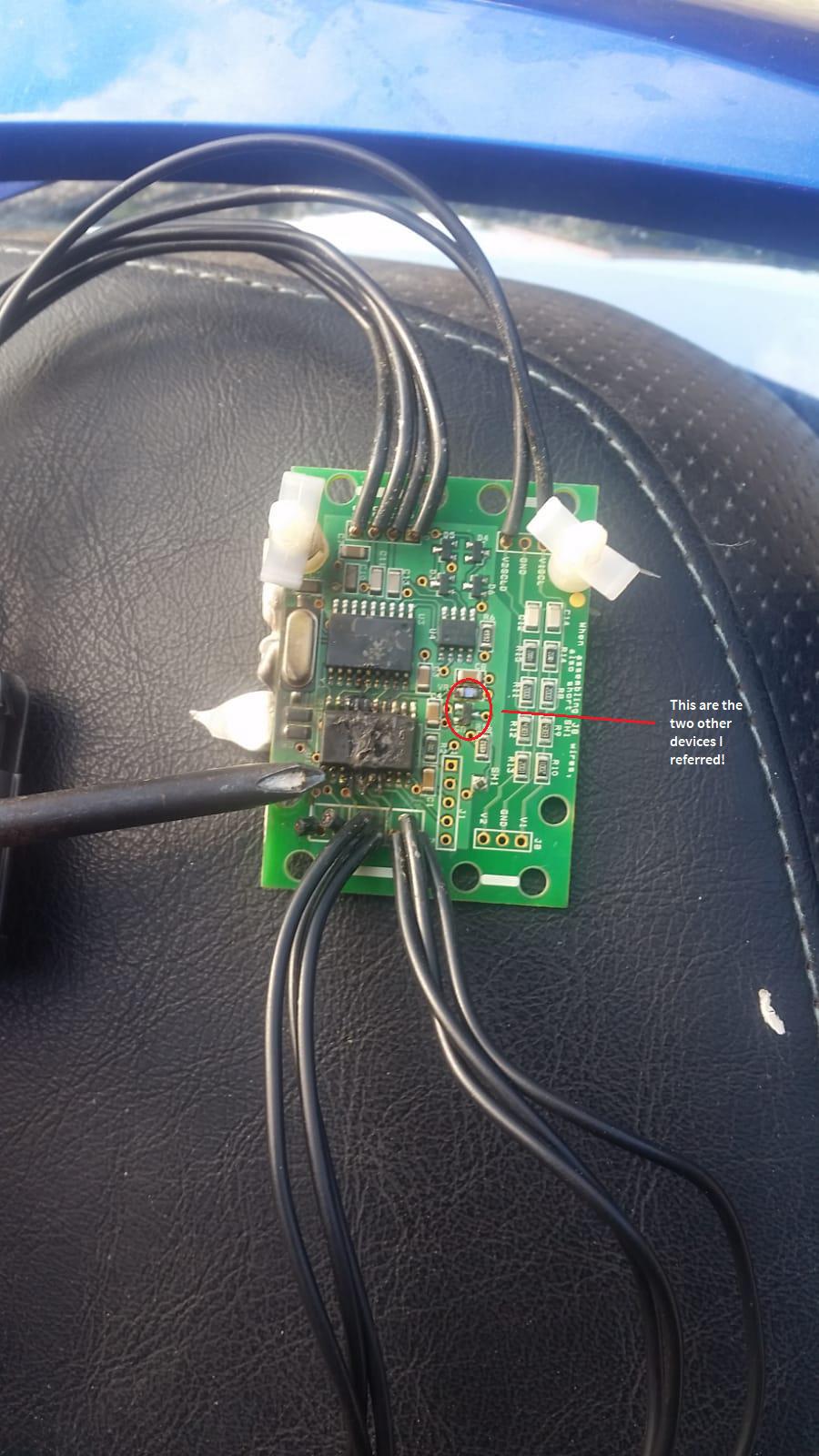
Let me confirm the smd marked code, as soon as I arrive home and then I let you know the P/N for order.
I used your picture and marked on red the other two devices to check. See image below!
Customer support service by UserEcho
Andrei,
In my case, I believe the sensors from both boards, were damaged by watwer or moisture and this lead the thermistors wiring to make contact with some battery terminals. Of course the microcontroller was the first to be sacrificed and all adjacent components were also damaged. The 5v supply for this board comes from the charger (IC201 - 5v regulator - L7805) which output was pratically shorted.
So, in your case, after replacing all damaged components from both boards and sensors, make sure your charger was not affected on the 5v circuitry. You can make a quick check by measuring the resistance on the two connectors that plugs on the front and rear boards (scooter wiring). See the images attached for reference (top view). In my case this value was 18 ohms - too low, almost a short! The expected value shall be around 14 Kohm.
I hope this helps you!