

Your comments

Hi,
Usually the ICMs are very reliable, personally I never had any problems with them. The 5V voltage regulator chip (U5) is Sharp 05DZ11.
/ Azzuro
Bonjour Lionel,
Great, thank you. We could use emails indeed for exchanging files which may not be of interest of the wider community indeed.
Meanwhile I've checked the encoder and I see conflicting statements if Hall sensors are in use or the angular detection only relies on the optical sensor. Some claim it is not in use and I don't see Hall elements on the pictures of the board either (I am not in the position here in Antibes to check it myself). On the other hand I see references to the Hall functionality in the pre-production versions of the MC firmware.

Salut Lionel,
I haven't had any problems with the encoder yet therefore I have little experience with it, however I will check the background this week to figure out how it works. In general I would expect signals on all 5 input ports (Hall A/B/C and ENC A/B).
Regarding the IGBT block, I don't have a layout diagram but it is fairly easy to find the respective optocouplers, they are next to the IGBT control pins on the PCB. On the other hand I have the circuit diagrams for the MC, please drop me an (email : vectrixshare@gmail.com) regarding those.
No worries for the patience, we are here to help each other :)
Bonjour Sylvain,
Yes I have the complete file, please send an email to the following address : vectrixshare@gmail.com
No probs at all - please find the page showing the relevant part of the MC. It is a fairly simple design with 3-3 opto gates driving the positive and negative sides of the IGBT for the 3 phases (U,V,W). B+ stands for the positive voltage of the battery.
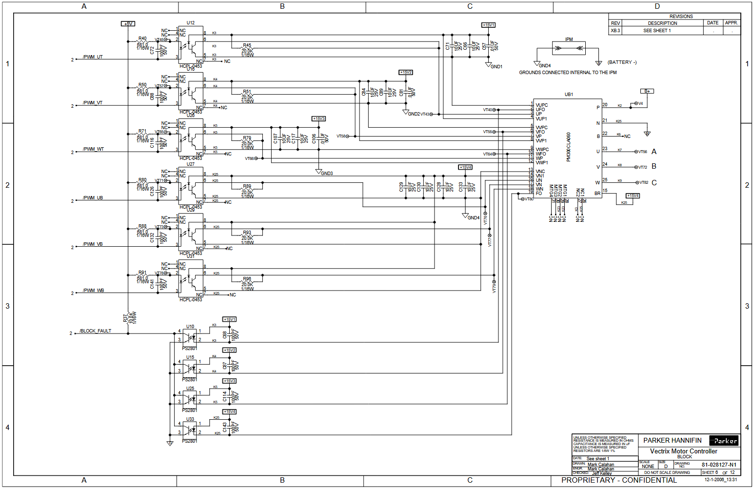
As shown in theory the IGBT fault should be detected (and the respective error displayed in the application and on the dashboard) but as far as I know this does not happen in all the cases. It is basically a logical OR function realized with the 4 gates shown.
Forgot to respond to your last remark. Feel free to share the pictures of the signals here in the blog - if something would not be clear we could agree to have a zoom call later as well.
Bonjour Lionel,
Mon français est loin d'être parfait encore, je vais donc continuer à utiliser l'anglais pour notre conversation. Apparently there are some promising news for the fuse of the supercapacitor and also with the cell voltages detection (I guess you've replaced the firmware on the MC).
Concerning the MC itself, yes there is a calibration function in the diag application under the Encoder tab. You could try to run the calibration (with the rear wheel lifted of course). Unfortunately based on the symptoms you've described - more precisely asymmetric behaviour between the 3 phrases - there is a chance it won't help. One of the weak points of these motor controllers is the IGBT module that drives the motor. While I've never had problems with those in my two scooters, this happens sometimes. I have a few broken MCs from other people with missing modules.
If it is defective the options are
(1) buying a used MC from internet, obviously there is no guarantee it will have a working IGBT
(2) replace the module (Mitsubishi PM300CLA060), the challenge is there is a row of control pins to be carefully desoldered
(3) fixing the IGBT module itself, the bad news is it is filled with epoxy
If you prefer to check the problem in more detail you can run additional tests with the oscilloscope including the input signals of the IGBT (https://www.alldatasheet.com/datasheet-pdf/pdf/161781/MITSUBISHI/PM300CLA060.html).
While I've never seen a defective motor it may be worth to check the resistance between the 3 coils on the motor itself.
Sure, glad you are making progress. Pas de neige ici à Antibes :)
I'd recommend to use the MCR2042-4.hex. My assumption is the Framuga MC firmware is not interpreting the CAN messages coming from the charger properly and limits the power as the result.
In general the MC with the stock firmware is capable to work in case there are proper cell voltage values coming from the BMS but also if these values are completely missing. On the other hand operation is disrupted in case there are forbidden values on the bus namely cell overvoltage or undervoltage. Could you check these values in diag mode : red kill switch on > left brake lever pulled once > red kill switch off - and the respective values displayed on the small LCD on the dashboard. Values like "0" and "nots" indicate wrong data on the bus.
Customer support service by UserEcho
Bonjour Lionel,
Apparently the access to the documents you wished to share is restricted, if you could grant permission please. Regarding the firmware, I haven't seen a note if it was replaced yet however if you still have the Framuga version that needs to be changed according to me as stated earlier.
Bien à vous, Azzuro